
The goal is understanding the message
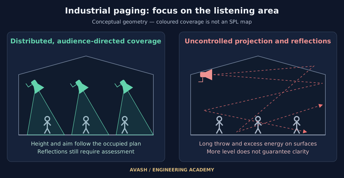
A familiar factory complaint is that paging is painfully loud, yet the announcement cannot be understood. Raising the level is often the first response. The underlying problem may instead involve reflections, background noise or unsuitable placement.
Sound pressure level, or SPL, describes the level reaching a location. Speech intelligibility concerns how well the message can be understood. Industrial design needs both, assessed under real production conditions.
Three mechanisms that obscure speech
1. Reverberation and hard surfaces
Concrete floors, metal cladding and many industrial finishes provide little absorption in parts of the spectrum. Late reflections can overlap subsequent syllables. RT60 describes a 60 dB sound decay after the source stops; it varies with frequency, room volume and absorption.
2. Spectral masking by machinery
Presses, compressors and production lines have different spectra. Noise in overlapping bands can mask speech components, so a single overall noise figure is insufficient for tuning. Mid-frequency bands, including parts of 1–4 kHz, are important to intelligibility, but assessment must consider the wider speech spectrum.
3. Arrival-time differences between sources
When two sources reproduce the same message at similar levels over different path lengths, their combination can create comb filtering. Greater delays may also become a separate audible repetition. There is no universal 30 ms boundary for echo perception: programme material, relative level and listening conditions matter.
From noise measurements to a paging target
Record zone noise during typical operation and noisy production periods. Occupied locations, temporal variation and noise spectrum matter more than floor area alone. The aim is intelligible speech at the listener, rather than the highest possible amplifier output.
A margin around 10 dB above ambient is a common starting point for industrial paging assessment; some briefs examine 10–15 dB. Such margins do not guarantee intelligibility. Check noise spectrum, reverberation, sound exposure constraints and field performance. Extremely noisy zones may also require visual notification or another complementary communication method.
Horn, projector or pendant: select for the space
Wattage alone is insufficient. Compare sensitivity, usable maximum output, frequency response and directivity across speech bands. High sensitivity is valuable in many horn designs, but a figure such as 105 dB cannot be generalised to every model.
Review the available sound projector data sheets and outdoor transducer documents. Match each model to the zone and installation conditions.
| Type | Application | Selection checkpoint |
|---|---|---|
| Horn | Paging in noisy zones and outdoor areas | Directivity and speech clarity; musical bandwidth varies by model |
| Sound projector | Corridors, warehouses and speech/music zones | Single- or bidirectional pattern, bandwidth and usable output |
| Pendant | Bringing the source closer to listeners below a high ceiling | Suspension safety, clearance, obstructions and coverage |
Specify protection for each environment
Match ingress protection to dust, wash-down, moisture, temperature and installation instructions. IP65 or IP66 may be required in particular locations, but neither is a universal minimum for every factory. Cable entries and connectors also form part of system protection.
An IP rating alone does not establish chemical corrosion resistance or suitability for an explosive atmosphere. Those conditions require specific equipment selection and supporting documentation.
Four placement principles
1. Distributed coverage at appropriate output
Bringing suitable sources closer to occupied areas can control near-to-far level differences and unnecessary energy on reflective surfaces. Derive count and taps from coverage and target level; adding sources alone does not guarantee clarity.
2. Aim at occupied listening areas
Set the aiming angle from mounting height, occupied width and the model’s actual pattern. Downward aiming is useful in many layouts; 30–45° is only a possible example. A concrete floor should not be assumed to be acoustically absorptive.
3. Coordinate mounting height with operations
A high roof mounting position can produce an unfavourable direct-to-reverberant ratio. Review lower column or pendant positions alongside cranes, forklifts, ventilation and maintenance access. A 3.5–5 m height range is not a universal design rule.
4. Control overlap and arrival time
Check relative levels and path differences in overlap areas. Aligned or staggered layouts can help; opposing layouts also require analysis of geometry and delay. DSP alignment is set for defined locations and scenarios, rather than eliminating every interference pattern throughout a room.
What makes the design dependable?
After installation, assess representative locations while machinery operates. Listening tests with real announcements and STI or STIPA measurements, as appropriate to the brief, help evaluate performance. Equalisation does not reduce the room’s reverberation time; source position, aiming and acoustic treatment also need consideration.
Use the coverage and placement calculator for an initial geometric estimate, then assess intelligibility on site. Explore the Depoint industrial project for an installation case study.
The next decision concerns transport and control. Read the networked industrial paging guide for the role of an audio matrix, 100 V circuits and hybrid architecture.