
Three steps from clarity to an acoustic blind spot
In a refined showroom, lobby or café, music can sound sharp directly beneath a ceiling transducer, then lose detail a few steps away. The ceiling is carefully designed and the equipment expensive, yet listening quality changes across the room.
The showerhead analogy helps describe hot spots and under-covered areas. Directivity is only part of the diagnosis: reflections, placement, level differences, polarity and tuning also matter. This guide focuses on one essential design input: transducer coverage angle.
Why more watts do not mean wider coverage
Power handling and sensitivity help estimate output level, but do not define its spatial distribution. Radiating size relative to wavelength, driver geometry, waveguides and crossover design influence directivity. As wavelength decreases, a radiating aperture can become more directional: beaming.
A flashlight is a useful analogy, rather than a universal rule. Low frequencies are not always omnidirectional, nor are high frequencies always narrow. Controlled narrow coverage can be useful under high ceilings or when limiting energy directed toward reflective walls.
How to read a coverage specification
A nominal 90° or 120° figure needs a frequency range and an attenuation criterion. A full included angle between −6 dB boundaries differs from a −3 dB angle. Horizontal and vertical coverage may also differ. Polar and beamwidth plots across frequency are more informative than an isolated brochure number.
Wider coverage does not automatically preserve SPL or reduce the required transducer count. Distance, sensitivity, power, target level and overlap belong in the same design. A brand-wide average angle would obscure those differences; selection starts with a specific model and a documented source.
Behind the grille: different engineering approaches
KEF Uni-Q and Tannoy Dual Concentric use coaxial arrangements to bring the origins of different frequency bands closer together. In Uni-Q, the tweeter sits at the acoustic centre of the mid/bass cone. This can improve off-axis integration, without making every model identical or eliminating room interference.
JBL, Bose Professional and Ecler offer model-specific approaches to wide or controlled coverage. JBL uses RBI in selected models to coordinate coverage across frequency bands. No single angle should be attributed to their entire ranges.
Some Monitor Audio architectural models use waveguides or aimable tweeters to coordinate coverage with listening positions. C-CAM describes driver construction; diaphragm material alone does not determine beamwidth. Aiming capability must be checked for the particular model.
| Brand / approach | Design intent | Selection checkpoint |
|---|---|---|
| KEF / Uni-Q | Coincident-source integration | Off-axis response and reference frequency |
| Tannoy / Dual Concentric | Model-specific coaxial directivity | Coverage and available level at mounting height |
| JBL / RBI in selected models | Coverage integration across bands | Exact model, frequency range and criterion |
| Ecler and Bose Professional | Different commercial installation patterns | Polar pattern, mounting and overlap |
| Monitor Audio / architectural and invisible | Integration with architectural finishes | Model data and finish installation instructions |
When the architect wants no visible grille
A frameless grille is not the final step in architectural integration. Some interiors require an uninterrupted ceiling. Invisible solutions from manufacturers including Sonance and Monitor Audio conceal the radiating surface within the wall or ceiling construction. The technology predates 2026; installation detailing remains central to its success.
An invisible finish does not establish 180° coverage. Off-axis behaviour depends on panel construction, frequency and the finish. Labels such as BMR or bending-wave should not be applied indiscriminately. Installation instructions, measured data and a representative mock-up provide a firmer basis for selection.
Monitor Audio IV140: integration behind the finish
IV140 supports concealed installation behind a thin plaster finish, with paint, light wallpaper or fabric. Finish type and thickness must follow the installation instructions; arbitrary timber coverings or filler thicknesses should not be assumed suitable. Test the installation before final closure.
Its integrated back box helps control performance and reduce rear leakage; it does not replace building sound insulation. Mounting depth, access, required output and adjacent rooms matter alongside appearance. We do not treat 180° as a verified calculator input for this model.
Before cutting the ceiling: use the effective height
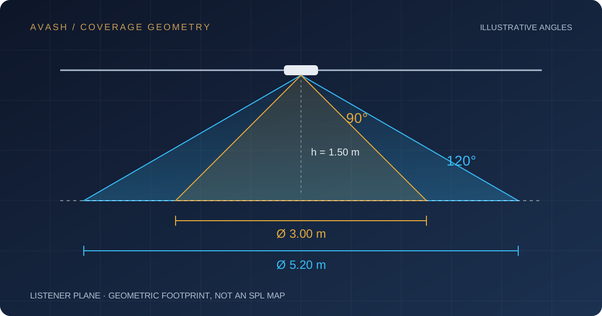
Assume a 3 m mounting height and a standing listener plane at 1.5 m. The effective separation is 1.5 m. For a vertically aimed, symmetric cone, a 90° angle gives a 3 m geometric diameter; 120° gives approximately 5.20 m. The illustration shows these hypothetical angles, rather than specifications of a particular product.
If the effective separation itself is 3 m, the diameters become 6 m and approximately 10.39 m. Ceiling height alone is therefore insufficient. This expression cannot be used unchanged for a 180° pattern or for wall-mounted and tilted arrangements.
h = H_mount − H_listener | diameter = 2 × h × tan(θ / 2)From coverage circles to a listening experience
Geometric circles are a layout starting point, not a measured SPL map. Useful coverage depends on spacing, overlap, aiming, frequency response and room reflections. Level and tonal balance are not constant inside each circle; a simple model cannot guarantee perfect uniformity.
In AVASH’s placement tool, enter room dimensions and listener height, compare currently available models and explore the effect of angle and spacing. Frequency-specific selection requires valid data for the selected model. Additional brands are a later development phase; their appearance in this guide does not imply that every model is already in the database.
- Define mounting and listener heights separately.
- Read angle, frequency and attenuation criterion together.
- Coordinate the layout with architecture and installation constraints before cutting.